


To troubleshoot source and calibrator failures
Use this test to isolate source and calibrator failures to the A6 Digital assembly, the
A5 Analog assembly, the A1/A2 Input assembly, the A12 BNC assembly, or the
A10 Rear Panel assembly.
Step 1. Check the sine wave output.
•
Set the power switch to on ( l ).
•
Connect an oscilloscope to the analyzer’s SOURCE connector using a BNC
cable.
•
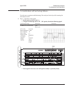
Set the oscilloscope as follows:
CH1 V/div
Input Impedance
CH1 Coupling
Probe Attenuation
Display Mode
Time/div
Trigger
Trig Src
Trigger Level
400 mV/div
50 Ω
dc
1
Repetitive
20 µs/div
Trg’d Sweep
Chan1
0V
•
Press the following keys:
[
System Utility ]
[
CALIBRATN ]
[
AUTO CAL OFF ]
[
Source ]
[
SOURCE ON ]
[
LEVEL ]
1
[ Vpk ]
•
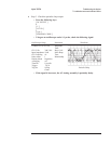
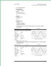
If the oscilloscope displays a 10.2 kHz, 2 Vp-p sine wave with no dc offset, go
to Step 2.
This is only a quick check of the source sine wave. If the source is suspected of
failing at a specific frequency or amplitude, check the source sine wave at the
failing frequency or amplitude.
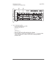
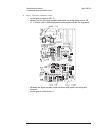
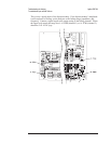
•
Using an oscilloscope and a 1:1 probe, check that the signal at A5 TP8 is a
10.2 kHz, 2 Vp-p sine wave with no dc offset.
•
If the signal is correct at A5 TP8 and incorrect at the analyzer’s front panel
SOURCE connector, the A12 BNC assembly is probably faulty.
•
If the signal is correct at A5 TP8 and incorrect at the analyzer’s rear panel
SOURCE connector, the A10 Rear Panel assembly is probably faulty.
•
If the signal is incorrect, the A5 Analog assembly is probably faulty.
Agilent 35670A Troubleshooting the Analyzer
To troubleshoot source and calibrator failures
4-45