


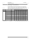
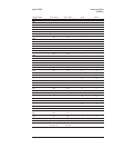
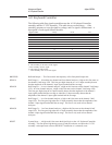

Signal Name
Pin(s) A8 P2 A9 J1
PROTCTn
A9 S •
PA18
C16 S •
PA19
A4 S •
PA20
A12 S •
PA21
B16 S •
PRW
A3 • •
VBATT
A13, A14, A15 S •
+5
A10, A11, B11, C11 • •
Gnd A1, A5, B5, C5, A7, A8
••
S This assembly is the source of the signal.
• This assembly uses the signal.
⇔ This signal is bidirectional.
— This assembly does not use this signal.
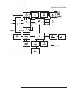
BASn Buffered Address Strobe — This line pulses low when a valid address is on the processor
address bus (PA0 — PA21).
MD24 — MD31 Memory Data Bus — This is the buffered processor data bus from the A7 CPU assembly. This
bus is further buffered on the A8 Memory assembly.
NVPRESn NRAM Present — A low on this line indicates that the A9 NVRAM assembly is connected to
the A8 Memory assembly. This line is checked only during manual troubleshooting
procedures.
OPRAMn Optional RAM — A low on this line enables the battery-backed static RAM on the
A9 NVRAM assembly.
PA0 — PA21 Processor Address Bus — This is the processor address bus from the A7 CPU assembly. This
bus is buffered on the A8 Memory assembly.
PROTCTn Protect — A low on this line disables the battery-backed static RAM on the A9 NVRAM
assembly. This line pulses low during power-up and power-down, when the A7 CPU
assembly’s microprocessor is externally reset, and when +5 volts on the A8 Memory assembly
is too low.
PRW Processor Read/Write — This line is high when the current memory cycle is a read and low
when the current memory cycle is a write.
VBATT Battery Voltage — This line provides the power to the battery-backed static RAM on the
A9 NVRAM assembly. When the analyzer is on, the +5 volts on the A8 Memory assembly
provides the power for this line. When the analyzer is off, the battery on the Memory assembly
provides the power for this line. Since power is applied to the static RAM even when the
analyzer is off, the static RAM is non-volatile.
Agilent 35670A Voltages and Signals
A9 NVRAM
9-13