


To perform initial verification
Use this test to check signals that are vital to the operation of the analyzer.
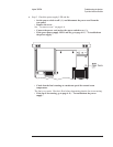
Step 1. Check the power select switch and fuse.
•
Check that the POWER SELECT switch on the rear of the analyzer is set to
the AC position.
•
Check that the correct line fuse is installed in the rear panel fuse holder.
For information on the power select switch and line fuse, see ‘’To do the incoming
inspection’’ on page 2-5 and ‘’To change the fuses’’ on page 2-10.
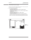
Step 2. If the grid appears after power up but there is no response when keys are
pressed, ckeck that the calibration routine is not locking up the analyzer.
•
Set the power switch to off ( O ).
•
Set the power switch to on ( l ) and as soon as Booting System appears on the
display, disable the calibration routine by holding [
Preset ] until Uncalibrated
data
appears.
•
If the keys are now active, go to page 4-37, ‘’To troubleshoot self-test lockup
failures.’’
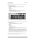
Step 3. If the analyzer powers up with failure messages, then locks up, but the grid
and lettering appear normal, go to page 4-15, ‘’To troubleshoot power-up failures.’’
Agilent 35670A Troubleshooting the Analyzer
To perform initial verification
4-5