


❑
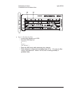
Step 5. Check the Input assembly.
•
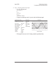
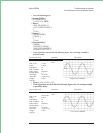
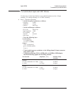
Using an oscilloscope and a 10:1 probe, check the following signal.
Oscilloscope Setup Parameters
Waveform
Connect CH1 to A1/A2 TP 300 Amplitude
Time
Distortion
Channel 1 Output
CH1 V/div
Input
Impedance
CH1 Coupling
Probe Atten
Display Mode
Averaging
Time/div
Trigger
Trig Src
200 mV/div
1M
Ω
dc
10
Repetitive
8
20 ms/div
Trg’d Sweep
Chan1
•
If the signal is incorrect, the A1/A2 Input assembly is probably faulty.
❑
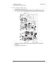
Step 6. Compare the analyzer’s self-test results to the following table.
•
Press the following keys:
[
System Utility ]
[
MORE ]
[
SELF TEST ]
[
FUNCTIONL TESTS ]
[
DIGITAL PROCESSOR ]
[
ALL ]
[
Rtn ]
[
ADC GATE ARRAY ]
•
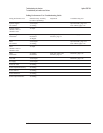
Determine the probable faulty assembly by comparing the analyzer’s
self-test results to the following table.
Self-Test Results Probable Faulty Assembly
Trigger Gate Array fails and ADC Gate Array passes A6 Digital
Baseband fails, Zoom fails, and ADC Gate Array passes A6 Digital
ADC Gate Array fails A5 Analog
All self tests pass through the ADC Gate Array A5 Analog
This test does not check all the signals from the A6 Digital assembly to the A5 Analog
and A1/A2 Input assemblies. All the functions of the A6 Digital assembly are checked
by the self tests except for a few output buffers. If replacing the A5 Analog assembly
does not fix the failure, the A6 Digital assembly is probably faulty.
Troubleshooting the Analyzer Agilent 35670A
To troubleshoot source and calibrator failures
4-50