


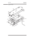

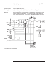
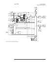
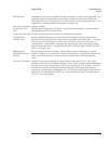

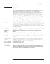

A1 Input
The A1 Input assembly is the input assembly for the two channel analyzer. The A1
Input assembly conditions the channel 1 and channel 2 input signals before they are
sent to the analog-to-digital converter on the A5 Analog assembly. The A1 Input
assembly sets the voltage ranges, conditions the input signals, and filters out alias
components. Signal conditioning is done with relays, high and low buffers, and a
series of amplifiers and attenuators. In addition, autozero DACs compensate for any
dc offset added to the signals by the circuits on this assembly. This assembly also
monitors the input signals for common mode or differential overloads and for
half-range conditions. Unless stated otherwise, the following description applies to the
block diagrams for both channel 1 and channel 2.
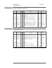
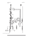
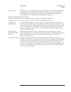
ICP Source Supplies power to transducers such as accelerometers when enabled. The ICP Source is a 4.25
1.5 mA floating current source. The power for the current source is obtained by switching the
15 V supplies at the sample frequency (262 kHz), isolating through a 1:1 transformer,
rectifying and filtering. When disabled, the source is disconnected by a relay and the switching
power supply is disabled.
Input Relays Select one of the 0 dB, 20 dB, or 40 dB pads and configure the input. The relays are controlled
by Relay Select & Energize.
Relay Select &
Energize
Selects and energizes the input relays. Relay Select & Energize is controlled by the IIC
Interface.
High Buffer Buffers the HIGH input signal (BNC center conductor). The High Buffer contains a bootstrap
circuit that prevents harmonic distortion and large common mode signals from saturating the
buffer.
Low Buffer Buffers the LOW input signal (BNC shell). The operation of the Low Buffer is identical to the
High Buffer.
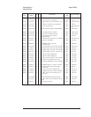
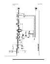
+10 dB Differential
Amplifier
Begins the gain and attenuation stages. This amplifier subtracts the HIGH and LOW input
signals from the high and low buffers. The common mode rejection adjustment, adjusts the
+10 dB Differential Amplifier to reject common mode signals.
0 /–12 dB Amplifier Can attenuate the signal by 12 dB.
0 /+14 dB Amplifier Can amplify the signal by 14 dB.
Step Attenuator Can attenuate the input signal from 0 dB to –14 dB, in 2 dB steps.
+2 dB Amplifier Adds a gain of 2 dB and allows the DC Offset DAC to vary the dc offset of the input signal.
The purpose of the amplifiers and attenuators up to this point is to ensure that the input signal
does not overdrive the anti-alias filter or analog-to-digital converter.
Circuit Descriptions Agilent 35670A
A1 Input
8-6