


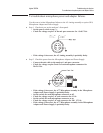

Step 2. Determine the probable faulty assembly or next step by comparing the trigger
failure to the following table.
If the trigger failure matches more than one entry in the table, use the entry closest to
the beginning of the table.
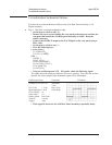
Trigger Mode Failing Probable Faulty
Assembly or Next Step
All channels and external trigger fail all trigger modes Step 3
All channels trigger but external trigger fails all trigger modes Step 4
At least one channel or external trigger functions correctly A5 Analog
Channel level fails
Arm fails
External trigger fails user level or TTL level
A5 Analog
External trigger fails EXT RANGE A10 Rear Panel
Trigger delay fails A6 Digital
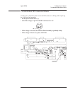
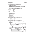
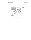
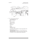
Step 3. Check trigger signal to Digital assembly.
•
Set the power switch to off ( O ).
•
Remove the A5 Analog assembly and attach a test clip patch cord to TP 204.
•
Connect a logic probe to the patch cord and TP 160 (ground).
• Reinstall the Analog assembly in the card nest with patch cord and probe
attached.
•
Set the power switch to on ( l ).
•
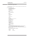
Press the following keys:
[
System Utility ]
[
CALIBRATN ]
[
AUTO CAL OFF ]
[
Input ]
[
ALL CHANNELS ]
[
CH* FIXED RANGE ]
1
[ Vpk ]
[
Source ]
[
SOURCE ON ]
[
LEVEL ]
[
1 ]
[
Vpk ]
[
System Utility ]
[
MORE ]
[
SERVICE TESTS ]
[
SPCL TEST MODES ]
[
SOURCE LEVEL ]
[
Trigger ]
[
CHANNEL 1 ]
Troubleshooting the Analyzer Agilent 35670A
To troubleshoot trigger failures
4-64