


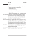
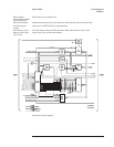
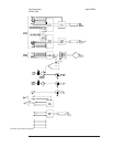
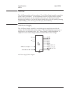

A10 Rear Panel
The A10 Rear Panel assembly contains the BNC connectors for the external trigger
input, tachometer input, and source output. The Rear Panel assembly also contains
DIN, GPIB, serial, and parallel interface connectors. In addition, the Rear Panel
assembly provides the fan control for the A90 Fan assembly.
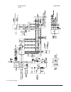
GPIB Controller and
Buffers
Allow the analyzer to communicate with devices such as plotters, printers, or a host computer
via an GPIB cable. These circuits handle all GPIB functions for the analyzer.
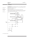
Parallel Port Controller
and Buffers
Allow the analyzer to send data to printers with Centronics interfaces.
IIC Processor Provides the interface from the DIN keyboard connector to the A7 CPU assembly. The IIC
Interface also decodes the control lines for the DAC.
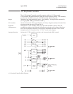
DAC Sets the tachometer trigger level. The A7 CPU assembly sends the control signals to the Rear
Panel assembly over the IIC bus. The IIC Processor decodes the control signals.
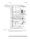
Tachometer Comparator Compares the input signal from the Tachometer BNC connector with the trigger level set by the
DAC. The output of the comparator changes TTL levels when the input signal crosses the
trigger level.
External Trigger Buffer Buffers the external trigger signal.
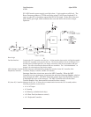
Fan Control Provides the A90 Fan assembly with a voltage that controls the fan speed. A temperature
sensor provides a control signal that changes with the analyzer’s internal temperature. When
the temperature increases, Fan Control increases the fan speed. When the temperature
decreases, Fan Control decreases the fan speed. Control lines from the A7 CPU assembly can
also set the fan speed to high or turn the fan off.
Serial Driver Drives the serial data lines to and from devices connected to the Serial Port. The serial port is
only available using Instrument Basic.
Agilent 35670A Circuit Descriptions
A10 Rear Panel
8-33