


To troubleshoot input and ADC failures
Use this test to isolate input failures in two channel analyzers to the A1 Input
assembly, A5 Analog assembly, or A12 BNC assembly.
Step 1. Check the input path.
•
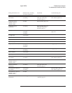
Set the frequency synthesizer as follows:
Frequency
Amplitude
Function
10 kHz
2 Vp-p
Sine Wave
•
Set the oscilloscope as follows:
CH1 V/div
Input Impedance
CH1 coupling
Time/div
Probe Atten
400 mV/div
1MΩ
dc
20 ns/div
1
•
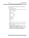
Press the following keys:
[
System Utility ]
[
CALIBRATN ]
[
AUTO CAL OFF ]
[
Input ]
[
ALL CHANNELS ]
[
CH* FIXED RANGE ]
1
[ Vpk ]
•
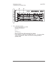
Connect the frequency synthesizer to the failing channel’s input connector
using a BNC cable.
•
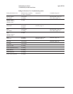
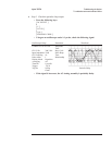
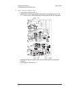
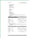
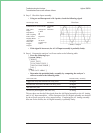
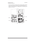
Using the oscilloscope, BNC-to-SMB cable, and SMB-to-SMB adapter,
check the following signals for the failing channel:
Test Location
Amplitude ( 10%)
Probable Faulty
Assembly
Channel 1
A12 P31 (connected to A1 P100)
A1 P200
2 Vp-p
2.83 Vp-p
A12 BNC
A1 Input
Channel 2
A12 P41 (connected to A1 P600)
A1 P700
2 Vp-p
2.83 Vp-p
A12 BNC
A1 Input
Agilent 35670A Troubleshooting the Analyzer
To troubleshoot input and ADC failures
4-51