


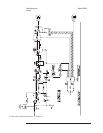
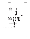
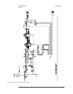
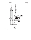

A6 Digital
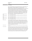
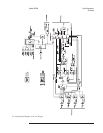
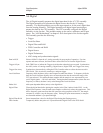
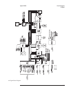
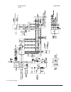
The A6 Digital assembly prepares the digital input data for the A7 CPU assembly.
The Digital assembly also generates the digital source data for the A5 Analog
assembly. The Digital assembly receives the input signals as 16-bit serial, digital data
from the Analog assembly. The Digital assembly uses digital signal processing to
prepare the data for the CPU assembly. The CPU assembly configures the Digital
assembly via the fast bus. This includes setting up the source, calibrator, and all gate
arrays. See “A99 Motherboard” in chapter 9 for a description of the fast bus signals.
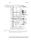
This assembly provides the following:
•
Trigger
•
Local Oscillator
•
Digital Filter and RAM
•
FIFO Controller and RAM
•
Digital Source
•
Digital Tachometer
•
ADC timing and synchronization signals
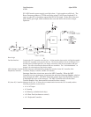
Data in MUX Selects ADDATA from the A5 Analog assembly for most modes of operation. For time
capture and some self-tests, the Data in Mux selects SRCDATA from the Digital Source.
Trigger & Sync Pulls TRIGI low to inform the Trigger circuit that the selected trigger occurred. Synchronizes
the ADC (on the A5 Analog assembly), Digital Source, Digital Tach, and Trigger Gate Array.
Trigger Gate Array Synchronizes data transfer by telling the FIFO Controller when to collect the time record in
FIFO RAM. This circuit also controls pre- and post-trigger.
Local Oscillator Frequency shifts the data to allow start frequencies other than 0 hertz. To frequency shift the
data, the Local Oscillator digitally mixes or heterodynes the data down into the range of the
FFT span selected. This makes the data complex and the sample is now represented by two
serial, digital signals — REALO and IMAG. During baseband measurements (where the start
frequency is 0 hertz), the data is only scaled through the Local Oscillator.
Dither PAL Adds span-dependent dither (noise) to the digital data.
Digital Filter Filters the digital data before placing the samples in the Filter Latches for the FIFO. As the
Digital Filter operates, it may discard some samples to effectively reduce the sample rate. This
allows frequency spans narrower than full span (due to the properties of the FFT, the sample
rate must be varied to vary the frequency span). During full span measurements, no samples
are discarded and data is just passed through.
Digital Filter RAM Stores intermediate values for the Digital Filter during the filtering process.
Filter Latches Temporarily hold a data point as it is passed from the Digital Filter to the FIFO RAM.
Circuit Descriptions Agilent 35670A
A6 Digital
8-22