


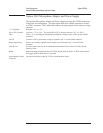

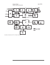
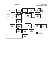
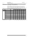
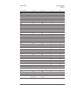
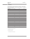
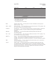

Power Supply Voltage Distribution
The following table shows the power supply voltages used by each assembly in the
analyzer. In addition, the table also shows the path taken by these voltages. Some
assemblies use the power supply voltages as supplied by the Power Supply assembly.
However, most assemblies contain voltage regulation and voltage decoupling circuits
to provide additional regulation and decoupling for their own use.
From Path To
Voltages
+18 V –18 V +12 V +8 V +5 V Gnd
Pwr Supply
W5 A99
••••••
W5/A99 A1/A2
••••
W5/A99 A5
•• •••
W5/A99 A6
••
W5/A99/W7 A10
••• ••
W5/A99 A90
••
W5/A99 A7
•• ••
W5/A99/A7 A8
•••
W5/A99/A7/A8 A9
••
W5/A99/A7/W6 A11
••
W5/A99/A7/W6/A11 A13
••
W5/A99/A7/W6/A11 A14
•
W5/A99/A7/W8 A100
••
W5/A99/A7/W6 A101
•••
W5/A99/A7/W6 A102
•••
Voltages and Signals Agilent 35670A
Power Supply Voltage Distribution
9-6