


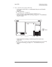
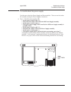

To troubleshoot power-up failures
Use this test when the screen is defective, when the analyzer does not respond
correctly to the keyboard, or when it takes more than 3 minutes for the keyboard to
become active. Any of the following conditions may cause a power-up failure:
•
A defective CPU or Memory assembly.
•
A defective assembly connected to the CPU assembly causing a bus failure.
•
A defective cable between the CPU assembly and another assembly.
•
A defective control line.
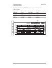
Step 1. Compare the power-up failure messages to the following table.
•
Set the power switch to on ( l ).
•
If the screen is blank or no power-up failure messages are displayed, go to
Step 2.
•
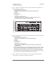
Determine the probable faulty assembly or next test by comparing the
power-up test result to the following table.
If the power-up failure messages match more than one entry in the table, use the
entry closest to the beginning of the table.
Failing Power-up Message Probable Faulty Assembly or Next Test
LEDs
MC68030 Processor
MC68882 Coprocessor
Bootrom
Display
A7 CPU
Main RAM
Program ROM
CPU, memory, DSP, and buses failures,
page 4-18
DSP A7 CPU
Fast bus IIC Bus failures, page 4-25
MFP A7 CPU
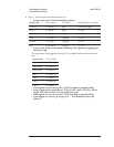
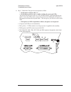
GPIB keypress detected, booting to GPIB Monitor A14 Secondary Keypad
Front Panel failure information:
keyboard IIC chip fails:
IIC: No Device Acknowledge
key stuck: 32
A11 Keyboard Controller
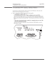
Front Panel failure information:
key stuck: number
where number is 13, 14, 16, 20, 21, 24, 33,
35, 36, 37, 38, 40, 43, 52, 53, or 54
A14 Secondary Keypad
Front Panel failure information:
key stuck: number
all other numbers not listed above
A13 or A15 Primary Keypad
Agilent 35670A Troubleshooting the Analyzer
To troubleshoot power-up failures
4-15