


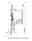
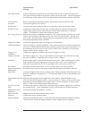
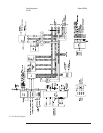
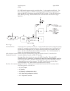

FIFO Controller Gathers the data from the Filter Latches when the selected trigger occurs and places the data
into FIFO RAM. After a time record is collected, this circuit controls data flow from FIFO
RAM to the CPU.
FIFO RAM Stores data from the Digital Filter. When the FIFO RAM has a complete time record, the FIFO
Controller pulls FIFOBAVn low to inform the A7 CPU assembly that a block of data is ready
for transfer.
FIFO Latches Hold a data sample until the Fast Bus Interface is ready to transfer the sample.
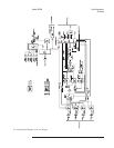
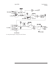
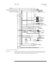
Digital Source and
RAM
The A7 CPU assembly loads the Digital Source RAM by putting the data needed by the Digital
Source into main memory (on the A8 Memory assembly). The CPU assembly then performs a
memory-to-memory DMA transfer from main memory to Digital Source RAM via the fast bus.
This data represents any source type except random, pink, or fixed sine which are generated
internally by the Digital Source. Any source type, except fixed sine, will be
frequency-translated and bandwidth-limited to correspond to the instrument frequency range.
Digital Tachometer and
RAM
Counts and stores the buffered tachometer pulses (BTACH) from the A10 Rear Panel
assembly. At the start of a measurement, GASYNC sets the Digital Tachometer’s counter to
zero. The counter starts counting and the tachometer signal latches the counter outputs. The
latched tachometer times are stored in RAM and read over the Fast Bus Interface by the A7
CPU assembly as needed.
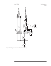
Frequency Reference Provides all clocks and timing for the gate arrays, Trigger & Sync, Digital Source, and Digital
Tach. In addition, the Frequency Reference generates PREFS and H10MHZ to synchronize
data transfers from the ADC on the A5 Analog assembly, and FSDIV2 for the A98 Power
Supply assembly.
Fast Bus Interface Connects the A6 Digital assembly to the fast bus. The fast bus transfers time records from
FIFO RAM to the A7 CPU assembly for processing. The fast bus is also used by the CPU
assembly to read tachometer data, to send time capture data or source data to the Digital
Source, and to configure the Trigger, Local Oscillator, Digital Filter, FIFO Controller, Digital
Source and Digital Tachometer.
Circuit Descriptions Agilent 35670A
A6 Digital
8-24