


A101 Display
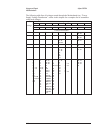
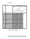
The following table lists signals routed between the A102 DC-DC Converter assembly
and the A101 Display assembly. This table shows several things — if the assembly
generates or uses the signal or voltage, and if a signal is bidirectional. A description of
each signal follows the table.
Signal Name
Pin(s) A102 A101
HSYNCELn
11 • •
PSENBLn
18 • S
VCLK
15 • •
VID
13 • •
VSYNCEL
9••
+215 V
4S•
-175 V
1S•
+40 V
5S•
+20 V
17 S •
+12 V
6••
+5 V
7••
Gnd
2, 3, 12, 14, 16 • •
Not Used
19, 20 — —
S This assembly is the source of the signal.
• This assembly uses the signal.
— This assembly does not use this signal.
HSYNCELn Horizontal Synchronization — A low on this line causes a horizontal retrace on the
A101 Display assembly. Between each HSYNCELn pulse, 560 pixels are sent to the Display
assembly.
PSENBLn Power Supply Enable — A low on this line enables the A102 DC-DC Converter assembly’s
power supply. The power supply generates the driver supply voltages. The driver supply
voltages are +20 V, +40 V, +215 V, and −175 V.
VCLK Video Clock — This 20 MHz clock provides the timing reference for HSYNCELn, VID, and
VSYNCEL. The rising edge of this clock determines setup and hold times.
VID Video Data — This is the serial data line for the A101 Display assembly. This line transmits
video data to the Display assembly. The video data is transmitted at the VCLK rate between
horizontal and vertical retraces (during the time HSYNCELn is high and VSYNCEL is low).
Only the first 400 lines of data are displayed after a VSYNCEL pulse.
VSYNCEL Vertical Synchronization — A high on this line causes a vertical retrace on the A101 Display
assembly.
Voltages and Signals Agilent 35670A
A101 Display
9-36