


A13 Primary Keypad
The A13 Primary Keypad assembly contains the marker, display, numeric, and
measurement keys for the two channel analyzer. The Primary Keypad assembly also
contains the RPG and the LEDs that indicate a half range or overload condition on a
channel. See ‘’A11 Keyboard Controller’’ for additional information.
A14 Secondary Keypad
The A14 Secondary Keypad assembly contains the system keys and the softkeys. See
‘’A11 Keyboard Controller’’ for additional information.
A15 Primary Keypad
The A15 Primary Keypad assembly contains the marker, display, numeric, and
measurement keys for the four channel analyzer. The Primary Keypad assembly also
contains the RPG and the LEDs that indicate a half range or overload condition on a
channel. See ‘’A11 Keyboard Controller’’ for additional information.
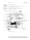
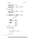
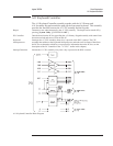
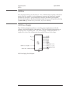
A22 BNC
The A22 BNC assembly connects the BNC connectors on the four channel analyzer’s
front panel to their respective assembly. The Channel 1 and Channel 3 BNCs are
connected to the A2 Input assembly connected to A99 J1. The Channel 2 and Channel
4 BNCs are connected to the A2 Input assembly connected to A99 J2. In addition, this
assembly provides RFI filtering for the HIGH and LOW inputs.
Agilent 35670A Circuit Descriptions
A13 Primary Keypad
8-37