


A11 Keyboard Controller
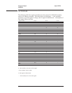
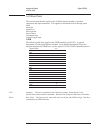
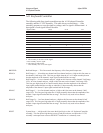
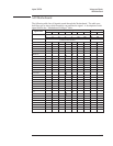
The following table lists signals routed between the A11 Keyboard Controller
assembly and the A7 CPU assembly. This table shows several things — if the
assembly generates or uses the signal or voltage, and if a signal is bidirectional. A
description of each signal follows the table.
Signal Name
Pin(s) A7 P1 A11
BBEEPER
3S•
HRNGA
11 — •
HRNGB
9—•
HRNGC
2—•
HRNGD
1—•
RESET
5S•
SCL
15 S •
SDA 13
⇔⇔
SINTFPn
7•S
+5 V
10 • •
Gnd 6, 8, 12, 14, 16
••
Not Used 4
——
S This assembly is the source of the signal.
• This assembly uses the signal.
⇔ This signal is bidirectional.
— This assembly does not use this signal.
BBEEPER Buffered Beeper — This line controls the frequency of the front panel beeper tone.
HRNGA Half Range A — In both the two channel and four channel analyzer, a high on this line turns on
the channel 1 half range LED. This line goes high when the A1 or A2 Input assembly detects
that the amplitude of the channel 1 input signal reached half the set range.
HRNGB Half Range B — In a two channel analyzer, a high on this line turns on the channel 2 half range
LED. In a four channel analyzer, a high on this line turns on the channel 3 half range LED.
This line goes high when the A1 Input assembly detects that the amplitude of the channel 2
input signal reached half the set range or when the A2 Input assembly detects that the
amplitude of the channel 3 input signal reached half the set range.
HRNGC Half Range C — In a four channel analyzer, a high on this line turns on the channel 2 half
range LED. This line goes high when the A2 Input assembly detects that the amplitude of the
channel 2 input signal reached half the set range. This line is only used in four channel
analyzers.
HRNGD Half Range D — In a four channel analyzer, a high on this line turns on the channel 4 half
range LED. This line goes high when the A2 Input assembly detects that the amplitude of the
channel 4 input signal reached half the set range. This line is only used in four channel
analyzers.
RESET System Reset — A high on this line resets the digital logic on the A11 Keyboard Controller
assembly. This line pulses high during power-up and power-down, and when the A7 CPU
assembly’s microprocessor executes the RESET instruction or is externally reset.
Voltages and Signals Agilent 35670A
A11 Keyboard Controller
9-18