


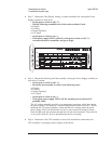

Step 2. Determine if the Digital, Analog, or Input assemblies are causing the Power
Supply assembly to shut down.
•
Set the power switch to off ( O ).
•
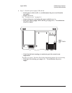
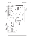
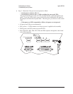
Pull the following assemblies out of the card nest about 1 inch:
A6 Digital
A5 Analog
A2 Input (optional)
A1/A2 Input
•
Set the power switch to on ( l ).
•
If the power supply LED is still off, set the power switch to off ( O ),
reconnect the above assemblies, and go to Step 4.
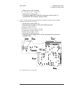
Step 3. Repeat the following until the assembly causing the Power Supply assembly to
shut down is located.
•
Set the power switch to off ( O ).
•
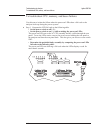
Reconnect one assembly at a time in the following order.
A6 Digital
A5 Analog
A2 Input (optional)
A1/A2 Input
•
Set the power switch to on ( l ).
•
If the green power supply LED is off, the assembly just reconnected is
probably faulty.
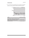
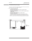
The A5 Analog assembly provides over-temperature protection which shuts down
the power supply if the analyzer’s internal temperature becomes excessive. Before
replacing the A5 Analog assembly, check that the fan is turning when the green
power supply LED is on and that the air flow is not restricted (cooling air enters
from the right side and exhausts through the left side and rear panel). Since the fan
is very quiet, check air flow to determine that the fan is turning.
Step 4. Determine if the CPU assembly or one of the assemblies connected to the
CPU assembly is causing the power supply to shut down.
Troubleshooting the Analyzer Agilent 35670A
To troubleshoot the power supply
4-12