


To troubleshoot intermittent failures
Use this test to isolate intermittent failures to the assembly.
•
Determine if your intermittent failure is caused by one of the following
common causes.
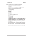
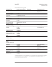
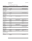
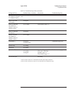
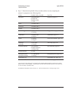
Common Reasons Troubleshooting Procedure
Loose screws
and cables
Check that the screws in the analyzer are tight and that the cables are
firmly in their sockets. This is especially important since grounding for
the analyzer depends on the cables and screws.
Motherboard
connectors
Remove each assembly connected to the Motherboard and check the
connectors for loose or bent pins.
Power supply
voltages
Check for correct power-supply voltages. See ‘’To perform initial
verification’’ on page 4-5.
Out-of-adjustment Do the adjustments for the analyzer in chapter 5.
Low level noise Do ‘’To troubleshoot distortion failures’’ on page 4-56.
Air flow
restricted
Cooling air enters from the right side and exhausts through the left side
and rear panel. Check that the air flow was not restricted in these areas
when the failure occurred.
External voltage Verify that the line voltage is within the electrical specification for the
analyzer. See chapter 2.
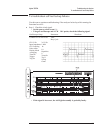
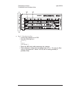
• Connect the rear panel SOURCE output to the rear panel TACH input using a
BNC cable. Remove all cables from the front panel input connectors.
Caution The ICP self test outputs approximately 30 Vdc on the input connectors. Before
starting the self tests, disconnect all devices connected to the input connectors.
Devices left connected during the ICP self test may be damaged.
•
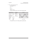
Set the power switch to on (
l ).
Troubleshooting the Analyzer Agilent 35670A
To troubleshoot intermittent failures
4-40