


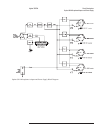

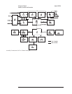

A1 Input
Analyzers with only two channels contain one A1 Input assembly. The A1 Input
assembly conditions both input signals. After the signals are conditioned by the Input
assembly they are routed through SMB cables to the A5 Analog assembly. The signal
from A1 P200 to A5 P4 is C1AAFO (Channel 1 Anti-Alias Filter Out). The signal
from A1 P700 to A5 P5 is C2AAFO (Channel 2 Anti-Alias Filter Out). The amplitude
of C1AAFO or C2AAFO is 1 Vrms with the analyzer set to the 1 dBVrms range and a
1.122 Vrms signal connected to the channel’s input connector.
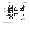
A2 Input
Analyzers with the four channel option contain two A2 Input assemblies. The A2
Input assemblies condition all four input signals. After the signals are conditioned by
the Input assemblies they are routed through SMB cables to the A5 Analog assembly.
For the Input assembly connected to A99 J1, the signal from A2 P200 to A5 P4 is
C1AAFO (Channel 1 Anti-Alias Filter Out) and the signal from A2 P700 to A5 P6 is
C3AAFO (Channel 3 Anti-Alias Filter Out). For the Input assembly connected to A99
J2, the signal from A2 P200 to A5 P5 is C2AAFO (Channel 2 Anti-Alias Filter Out)
and the signal from A2 P700 to A5 P7 is C4AAFO (Channel 4 Anti-Alias Filter Out).
The amplitude of C1AAFO, C2AAFO, C3AAFO, or C4AAFO is 1 Vrms with the
analyzer set to the 1 dBVrms range and a 1.122 Vrms signal connected to the
channel’s input connector.
Agilent 35670A Voltages and Signals
A1 Input
9-7