


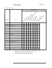
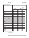

DC-Offset Tables and Frequency Correction Curves
The dc-offset calibration builds 5 dc-offset tables — one for each anti-alias filter and
one for each channel when the anti-alias filters are bypassed. The values in the
dc-offset tables are sent to the channel dc-offset DACs to compensate for dc offsets
introduced by analog input circuits. Forty values are entered in each table — a value
for each range setting from –51 dB to +27 dB, in 2 dB increments. For each range, the
table value is derived by changing the offset values of the dc offset DAC until the best
possible offset compensation is found. In all instrument modes, the analyzer corrects
for dc offsets by setting each channel’s dc-offset DAC to the value from the table that
matches the current anti-alias filter and range setting.
The frequency calibration generates correction curves in the frequency domain to
compensate for unflatness in the analog input circuits. A precise signal is connected
from the source to the input channels via the calibration path (CALP). Correction
curves are then produced for each range setting by taking the difference between the
source output and the measured response. In FFT analysis, correlation analysis, and
swept sine instrument modes, the analyzer multiplies the measured result with the
value from the frequency correction curve that matches the current range and span
setting. In this way, errors introduced by circuits in the analyzer are removed before
the measurement is displayed.
Internal Test Descriptions Agilent 35670A
Calibration Routine Description
10-6