


A14 Secondary Keypad
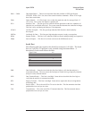
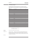
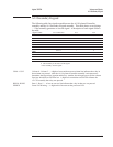
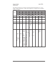
The following table lists signals routed between the A11 Keyboard Controller
assembly and the A14 Secondary Keypad assembly. This table shows several things
— if the assembly generates or uses the signal. A description of each signal follows
the table.
Signal Name
A11 Connection A11 A14
COL0
P2 Pin 3 • S
COL1
P2 Pin 2 • S
COL2
P2 Pin 1 • S
ROW0
P3 Pin 3 • S
ROW1
P3 Pin 2 • S
ROW2
P3 Pin 1 • S
ROW3
P4 Pin 3 • S
ROW4
P4 Pin 2 • S
ROW5
P4 Pin 1 • S
PWRFW
P5 Pin 3 S •
GND
P5 Pin 1 • •
S This assembly is the source of the signal.
• This assembly uses the signal.
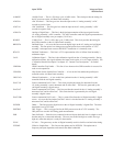
COL0 - COL2 Column 0 - Column 2 — A high-to-low transition on one column line indicates that a key in
that column was pressed. After the A11 Keyboard Controller assembly’s microprocessor
determines the keypad row location and the key number, the microprocessor sets the column
lines low which forces SINTFPn low. A high-to-low transition on SINTFPn informs the
A7 CPU assembly that a key was pressed.
ROW0 - ROW5 Row 0 - Row 5 — A low on one row line indicates that a key in that row was pressed.
PWRFW Power Fail Warning — A high on this line turns on the power-on LED.
Agilent 35670A Voltages and Signals
A14 Secondary Keypad
9-23