


To troubleshoot tachometer failures
Use this test to isolate tachometer failures to the A10 Rear Panel assembly or A6
Digital assembly.
Step 1. Check the rear panel tachometer input.
•
Set the power switch to off ( O ).
•
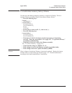
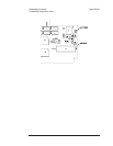
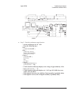
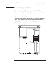
Remove the seven screws holding the rear panel to the analyzer and lean the
rear panel back until the A10 Rear panel assembly is visible. Keep the
cables connected.
•
Connect the SOURCE output to the TACH input on the rear panel using a
BNC cable.
•
Set the power switch to on ( l ).
•
Press the following keys:
[
System Utility ]
[
CALIBRATN ]
[
AUTO CAL OFF ]
[
Rtn ]
[
MORE ]
[
SELF TEST ]
[
LOOP MODE ON ]
[
FUNCTIONL TESTS ]
[
TACHOMETR ]
[
CONTINUE ]
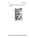
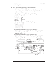
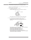
• Using an oscilloscope and 1 M 10:1 probe, check the following signal.
The signal should be displayed while the self test is running. Each time the self test
restarts, the source output to the tachometer input will be interrupted.
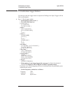
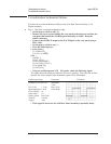
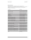
Oscilloscope Setup Parameters Waveform
Connect CH1 to A10 TP1 Amplitude
Time
Duty Cycle
Pulse shape
CH1 V/div
Input Impedance
CH1 Coupling
Probe Atten
Display Mode
Time/div
Trigger
1 V/div
1MΩ
dc
10
Real Time
2 ms/div
Auto
•
If the signal is incorrect, the A10 Rear Panel assembly is probably faulty.
Troubleshooting the Analyzer Agilent 35670A
To troubleshoot tachometer failures
4-70