


For the optional four channel analyzer, do the following to adjust common mode
rejection:
•
Set the power switch to off ( O ).
•
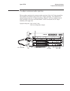
Connect the BNC(f)-to-minigrabber adapter to the BNC cable. Connect
both minigrabber clips (signal and ground) to A5 TP8 and the BNC
connector to the analyzer’s CH 1 connector.
•
Set the power switch to on ( I ).
•
Press the following keys:
[
System Utility ]
[
MORE ]
[
SERVICE TESTS ]
[
ADJUSTMTS ]
[
CHANNEL 1 ADJUSTMNT ]
[
CMRR ]
Wait for the analyzer to set up the adjustment. The analyzer is ready when
the adjustment message appears on the screen.
•
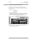
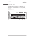
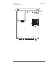
While monitoring the Y: value, adjust A2 R43 in the lower slot for a
minimum marker value.
•
Disconnect the BNC cable from the analyzer’s CH 1 connector and connect
to the CH 2 connector.
•
Press the the following keys:
[
Rtn ]
[
CHANNEL 2 ADJUSTMNT ]
[
CMRR ]
Wait for the analyzer to set up the adjustment. The analyzer is ready when
the adjustment message appears on the screen.
•
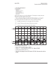
While monitoring the Y: value, adjust A2 R43 in the upper slot for a
minimum marker value.
•
Disconnect the BNC cable from the analyzer’s CH 2 connector and connect
to the CH 3 connector.
•
Press the the following keys:
[
Rtn ]
[
CHANNEL 3 ADJUSTMNT ]
[
CMRR ]
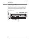
Wait for the analyzer to set up the adjustment. The analyzer is ready when
the adjustment message appears on the screen.
Agilent 35670A Adjusting the Analyzer
To adjust common mode rejection
5-15