


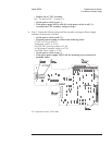
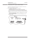

Step 3. Determine if the Memory or Display assembly is causing the failure.
•
Set the power switch to off ( O ).
•
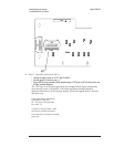
Reconnect the Memory assembly to the CPU assembly.
•
Set the power switch to on ( l ) while watching the power-on LEDs.
The LEDs should sequence through 00 (clear LEDs) with 00 remaining on the
LEDs.
•
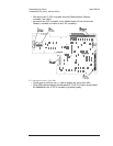
Set the power switch to off ( O ).
•
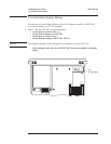
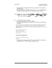
Reconnect the display cable to A7 P2.
•
Set the power switch to on ( l ) while watching the power-on LEDs.
The LEDs should sequence through 00 (clear LEDs) with 00 remaining on the
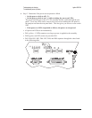
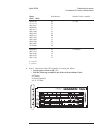
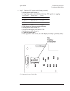
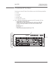
LEDs. The following is an example of the messages displayed when the CPU and
memory power-on tests pass. The numbers in the messages will most likely be
different in your analyzer.
Copyright 1988, 1990, 1991, 1992, 1993,
Agilent Technologies Company,
All rights reserved.
LEDs
MC68030 Processor
MC68882 Coprocessor
Bootrom revision A.01.17
Main RAM
Testing 8388608 bytes at 0x06c00000
Program ROM
Copyright 1991, 1992, 1993, Agilent Technologies Company
Booting System
•
If the screen is defective or blank, go to page 4-22, ‘’To troubleshoot display
failures.’’
•
If there is an error message, use the table on page 4-15 in the ‘’To
troubleshoot power-up failures’’ procedure to determine the probable faulty
assembly.
•
If the failure still is not isolated, go to page 4-25, ‘’To troubleshoot IIC bus
failures.’’
Agilent 35670A Troubleshooting the Analyzer
To troubleshoot CPU, memory, and buses failures
4-21