


•
Press the following keys:
[
System Utility ]
[ CALIBRATN ]
[ AUTO CAL OFF ]
[ Input ]
[ ALL CHANNELS ]
[ CH* FIXED RANGE ]
1
[ Vpk ]
[ Source ]
[ SOURCE ON ]
[ LEVEL ]
1
[ Vpk ]
[ System Utility ]
[ MORE ]
[ SERVICE TESTS ]
[ SPCL TEST MODES ]
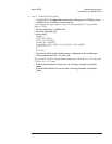
[ HIGH LEVEL CAL ]
•
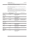
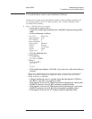
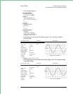
If the signal does not look like the following figure, the A5 Analog assembly is
probably faulty.
Oscilloscope Setup Parameters
Waveform
Connect CH1 to A1/A2 TP 17 Amplitude
Time
High Level Calibrator
CH1 V/div
Input
Impedance
CH1 Coupling
Probe Atten
Display Mode
Averaging
Time/div
Trigger
Trig Src
2 V/div
1MΩ
dc
10
Repetitive
8
20 ms/div
Trg’d Sweep
Chan1
•
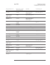
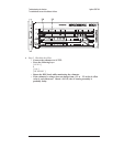
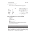
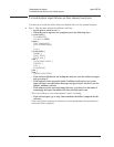
Press [ LOW LEVEL CAL ].
•
If the signal does not look like the following figure, the A5 Analog assembly
is probably faulty.
Oscilloscope Setup Parameters
Waveform
Connect CH1 to A1/A2 TP 17
Amplitude
Time
Low Level Calibrator
CH1 V/div
Input
Impedance
CH1 Coupling
Probe Atten
Display Mode
Averaging
Time/div
Trigger
Trig Src
200 mV/div
1MΩ
dc
10
Repetitive
8
20 ms/div
Trg’d Sweep
Chan1
Agilent 35670A Troubleshooting the Analyzer
To troubleshoot source and calibrator failures
4-49