


Step 2. Determine if the power-on test passed or failed.
•
Set the power switch to off ( O ).
•
Set the power switch to on ( l ) while watching the power-on LEDs.
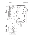
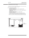
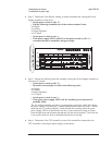
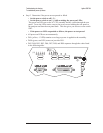
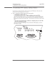
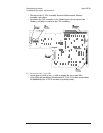
The power-on LEDs are on the A7 CPU assembly and are visible through the rear
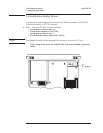
panel. To see the LEDs easier, remove the seven screws holding the rear panel to
the analyzer and lean the rear panel back. This also gives you access to reset switch
SW2.
•
If the power-on LEDs responded as follows, the power-on test passed.
•
All power-on LEDs are on momentarily.
•
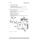
DS1 (yellow, +5 LED) remains on as long as power is applied to the assembly.
•
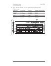
DS10 (green, run LED) comes on just after DS1.
•
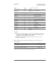
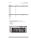
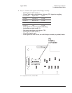
DS5, DS4, DS3, DS2, DS6, DS7, DS8, and DS9 sequence through the codes listed
in the following table.
Troubleshooting the Analyzer Agilent 35670A
To troubleshoot power-up failures
4-16