


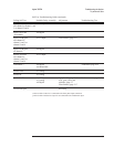
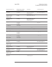
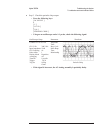

Failing Performance Test Probable Faulty Assembly
(in order of probabilty)
Adjustment Troubleshooting Test
Amplitude linearity
one channel
A1/A2 Input
A5 Analog
Input dc offset, page 5-10
ADC gain, offset, and
reference, page 5-7
Input and ADC, page 4-51
Four channel, page 4-54
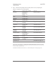
Amplitude linearity
channel 1 and 3 or
channel 2 and 4
A2 Input Input dc offset, page 5-10
Amplitude linearity
all channels
A5 Analog Input dc offset, page 5-10
ADC gain, offset, and
reference, page 5-7
Amp_phase match A1/A2 Input
A5 Digital
A6 Digital
Source and calibrator,
page 4-45
A-weight filter A1/A2 Input
Anti-alias filter A1/A2 Input Filter flatness, page 5-17
Frequency accuracy A7 CPU Frequency reference, page 5-5
Input coupling A1/A2 Input
Single ch phase accuracy A10 Rear Panel
A5 Analog
A6 Digital
Trigger, page 4-62
External trigger A10 Rear Panel
A5 Analog
Trigger, page 4-62
Input resistance A1/A2 Input
Input capacitance A1/A2 Input
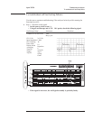
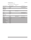
Harmonic distortion
one channel
A1/A2 Input
A5 Analog
Input and ADC, page 4-51
Four channel, page 4-54
Harmonic distortion
channel 1 and 3 or
channel 2 and 4
A2 Input
Harmonic distortion
all channels
A5 Analog ADC gain, offset, and
reference, page 5-7
Intermodulation distortion
one channel
A1/A2 Input
A5 Analog
Input and ADC, page 4-51
Four channel, page 4-54
Intermodulation distortion
channel 1 and 3 or
channel 2 and 4
A2 Input
Intermodulation distortion
all channels
A5 Analog ADC gain, offset, and
reference, page 5-7
Agilent 35670A Troubleshooting the Analyzer
To troubleshoot performance test failures
4-43