


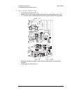
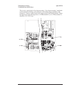


To troubleshoot distortion failures
Use this test to isolate distortion failures to the A1/A2 Input assembly, the A5 Analog
assembly, or to mechanical failures.
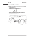
Step 1. Check mechanical ground connections.
•
Check that the Digital assembly, Input assembly, and Analog assembly are
completely in the card nest and making good contact with the grounding
guides at the sides of the card nest.
•
Check that the screws in the sides, back, and top of the analyzer are tight.
When grounding is inadequate, feedback from the line power frequency and
internal clock frequencies may appear as distortion on the Input assemblies.
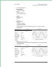
Step 2. Check the analyzer’s clock signals.
Noisy clock signals can cause noise or spurious signals in the analyzer. To check the
analyzer’s clocks, go to page 4-5 ‘’To perform initial verification’’ and do Step 6.
Step 3. Do the “Spurious signals” and ‘’Noise’’ performance tests.
•
Run the “Spurious signals” and ‘’Noise’’ performance tests in chapter 3,
‘’Verifying Specifications.’’
•
If all channels fail, the A5 Analog assembly is probably out of adjustment or
faulty.
Do the ‘’ADC gain, offset and reference’’ adjustment on page 5-7 before replacing
the assembly.
•
If only one channel, or channel 1 and 3, or channel 2 and 4 fails, the Input
assembly that failed is probably faulty.
•
If the ‘’Spurious signals’’ and ‘’Noise’’ performance tests pass, but the
analyzer appears to power up with a high noise floor, an auto-range circuit
may be failing.
To check the auto-range function and isolate a failure, see ‘’To troubleshoot
auto-range failures’’ on page 4-59.
Troubleshooting the Analyzer Agilent 35670A
To troubleshoot distortion failures
4-56