


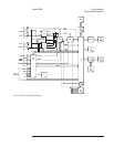
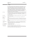

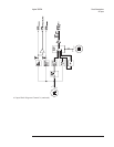
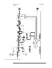
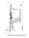

DC Offset DAC Compensates for any dc offset added to the input signal due to circuitry in the signal path. The
required dc offset is calculated during the analyzer’s calibration routine and is added to the
input signal in 0.3.45 mV increments by varying the dc offset at the inverting input of the
+2 dB Amplifier (see “Calibration Routine Description” in chapter 10).
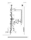
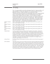
Anti-Alias Filter Bypass Bypasses all filters.
50 kHz Anti-Alias Filter Provides alias protection up to 50 kHz for two channel measurements.
25 kHz Anti-Alias Filter Provides alias protection up to 25 kHz for four channel measurements.
A-Weight Filter Provides additional filtering in the 25 kHz anti-alias filter path for acoustic measurements.
Analog Switch Selects one of four possible signals in the channel 1 or channel 2 input path to send to the ADC
— the signal through the Anti-Alias Filter Bypass, 50 kHz Anti-Alias Filter, 25 kHz Anti-Alias
Filter, or A-Weight Filter. In the channel 3 or 4 input path, the Analog Switch selects one of
three possible signals to send to the ADC — the Anti-Alias Filter Bypass, 25 kHz Anti-Alias
Filter, or the A-Weight Filter.
Half Range and
Differential Overload
Detectors
Sense the signal at the anti-alias filters. When a detector detects a half-range or overload
condition, a digital low is sent to the IIC Interface by the detector. The half-range detector also
sends a control signal to the A13 Primary Keypad assembly that lights an LED when a
half-range condition occurs.
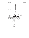
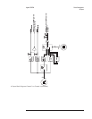
IIC (Inter-IC) Interface Contains 32 ports and connects the A2 Input assembly to the serial IIC bus. The A7 CPU
assembly uses the IIC bus to configure the input circuits. When a common mode or differential
overload occurs, the IIC Interface forces SINTn low to interrupt the CPU assembly. The CPU
assembly then reads the IIC Interface to determine the type of interrupt and the channel it
occurred on. During up/down autoranging, the A7 CPU queries the A1 Input assembly for half
range status. For a description of the IIC bus, see the description of the IIC Controller for the
“A7 CPU” later in this chapter.
Agilent 35670A Circuit Descriptions
A2 Input
8-13