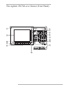
Agilent 35670A Front Panel
1-Use the softkeys to select items from the current menu. A softkey’s function is indicated by a video label on the analyzer’s screen.
Throughout this book, softkeys are printed like this: [
FFT ANALYSIS
].
Hardkeys are front-panel buttons whose functions are always the same. They have a label printed directly on the key itself.
Throughout this book, hardkeys are printed like this: [
Inst Mode
].
2-The analyzer’s screen is divided into the menu area and the display area. The menu area displays video labels for the softkeys. The
data area displays measurement data and information about the parameter settings.
3-The [
Rtn
] key returns the menu to the previous level.
4-The POWER switch turns on the analyzer.
5-Use the SYSTEM keys to control various system-level functions. These functions include saving files, plotting measurement data,
and accessing online help.
6-Use the disk drive to save your work on 3.5 inch flexible disks.
7-The knob moves the markers and the cursor. It also steps through numeric values and scrolls through online help.
8-Use the DISPLAY keys to control what appears on the analyzer’s traces. They only affect how data is displayed; DISPLAY keys
do not change measurement parameters.
You can press keys in the DISPLAY menus without losing measurement parameters.
9-Use the MARKER keys to select a variety of marker features.
10-Use the MEASUREMENT keys to control the analyzer’s source and inputs. They also control measurement parameters. You
must make a new measurement if you change a MEASUREMENT parameter.
11-Use the numeric-entry keys to enter a numeric value.
12-The microphone power connector provides power (8 Vdc) for the Microphone Adapter Kit (Option UK4).
13-The connector area of the front panel has two different configurations. The standard analyzer has a source output connector and
two input connectors. The 4-channel analyzer (Option AY6) has four input connectors.
Range indicators are located next to each input connector. The upper LED is the over-range indicator (the signal level exceeds the
current range setting). The lower LED is the half range indicator (the signal level exceeds half the current range setting).
14-A source on/off indicator is located at the left edge of the connector area.
The standard Agilent 35670A (2-channel) has a source connector on the front panel.


