


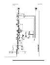
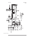

A5 Analog
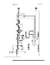
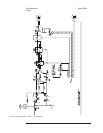
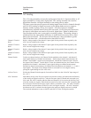
The A5 Analog assembly converts the analog input from the A1 Input assembly or A2
Input assemblies to 16-bit serial, digital data. The Analog assembly also converts
digital data from the A6 Digital assembly to the analog source output.
The input conversion process passes the analog inputs from all active channels through
an 8-bit ADC (analog-to-digital converter) twice adding dither (noise) to improve
linearity and the accuracy of low-level signals. All active inputs are sampled
simultaneously and held until all have been converted. For the first-pass conversion,
the input is scaled then converted to 8-bit serial, digital data. Dither is added to the
first-pass data and the sum is converted to an analog voltage. The analog voltage is
subtracted from the input and the difference is scaled then converted to 8-bit, serial
data in the second pass. The first-pass and second-pass values are added to get the
final 16-bit data word. A third conversion clears the 8-bit ADC.
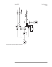
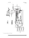
Channel 1 Track &
Hold
Holds a voltage sample of the channel 1 input signal for the period of time required by the
ADC circuits to digitize the voltage.
Channel 2 Track &
Hold
Holds a voltage sample of the channel 2 input signal for the period of time required by the
ADC circuits to digitize the voltage.
Channel 3 Track &
Hold
Holds a voltage sample of the channel 3 input signal for the period of time required by the
ADC circuits to digitize the voltage.
Channel 4 Track &
Hold
Holds a voltage sample of the channel 4 input signal for the period of time required by the
ADC circuits to digitize the voltage.
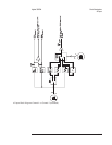
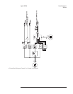
Channel Switch For the two channel analyzer, the Channel Switch multiplexes the channel 1 and channel 2
input signals during two channel measurements . During single channel measurements, the
channel 1 and channel 2 signals are not multiplexed. Instead, the Channel Switch is fixed to
the output of the Channel 1 Track & Hold. For the four channel analyzer, the Channel Switch
multiplexes the channel 1 and channel 2 input signals during two channel measurements.
During four channel measurements, the Channel Switch multiplexes the channel 1, 2, 3, and 4
input signals. The output of the Channel Switch is converted to a 16-bit digital word by
passing the signal through an 8-bit ADC twice.
1st Pass Circuit Divides the Channel Switch output by four and level shifts it to the 8-bit ADC input range of
0to−0.5 V.
ADC Controller Adds dither (noise) to the first pass signal to increase the accuracy and reduce the non-linearity
of the Analog-to-Digital conversion. After the first pass signal is filtered and converted to an
8-bit word, the ADC Controller adds the dither and outputs a 16-bit word to the 2nd Pass DAC.
After the second pass signal is filtered and converted to an 8-bit word, the ADC Controller adds
the second pass word to the first pass word to obtain a 16-bit data word. The ADC Controller
then sends the converted data as ADDATA to the A6 Digital assembly. The ADC Controller
also detects an ADC overload when the signal to the analog-to-digital converter is too high.
The overload information is sent as ADCOL and ADCUL to the A6 Digital assembly.
Circuit Descriptions Agilent 35670A
A5 Analog
8-18