


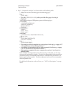
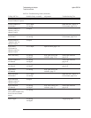

To troubleshoot fast bus failures
Use this test to isolate Fast Bus failures to the A7 CPU assembly or A6 Digital
assembly.
•
Set the power switch to off ( O ).
•
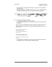
Set the power switch to on ( l ) while holding in the [ System Utility ] key.
The screen displays
Fast Bus Diagnostic Test ... and the power-on LEDs are flashing.
•
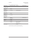
If the analyzer did not respond correctly, the A7 CPU assembly is probably
faulty.
•
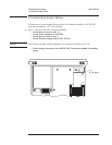
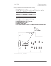
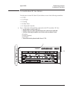
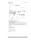
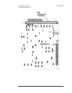
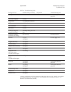
Using a logic probe, check the following signals.
A7 P10 Pin Signal Name TTL Logic State In Test Mode
64, 114, 65, 115, 66 FA1 to FA5 Toggling
72 ECLK Toggling
74 FSELAn Toggling
112 BRESETn Low
119 FRW Toggling
123 FIFOENn High
124 FSELSn Toggling
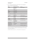
7-11, 21-45, 59, 71, 109,
118, 120, 122, 147, 149
GND Low
•
If the signals are correct, the A6 Digital assembly is probably faulty.
•
If any signal is incorrect, the A7 CPU assembly is probably faulty.
This is only a partial check of the fast bus signals between the A7 CPU assembly
and the A6 Digital assembly.
Agilent 35670A Troubleshooting the Analyzer
To troubleshoot fast bus failures
4-29