


Step 2. Check the dc offset DAC.
•
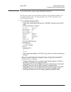
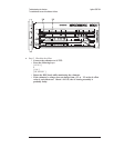
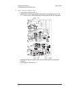
Using the BNC-to-SMB cable, connect the oscilloscope to A1 P200 to check
channel 1 or to A1 P700 to check channel 2.
If you changed the input signal or range, set the input signal to 2 Vp-p and the
range to 1 Vpk.
•
Set the oscilloscope to 700 mV/div.
•
Press the following keys:
[
System Utility ]
[
MORE ]
[
SERVICE TESTS ]
[
SPCL TEST MODES ]
[
MORE SPCL MODES ]
[
CHANNEL 1 SPCL MODE ]or[CHANNEL 2 SPCL MODE ]
[
OFFSET DAC ]
0
[ ENTER ]
•
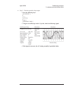
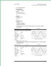
Note the dc offset voltage of the sine wave displayed on the oscilloscope.
•
Enter numbers between 127 and +128.
The sine wave dc offset voltage should change about 780 mV for a −127 entry and
−780 mV for a +127 entry.
•
If the dc offset function is incorrect, the A1 Input assembly is probably
faulty.
•
If the dc offset function is correct, the A5 Analog assembly is probably
faulty.
Agilent 35670A Troubleshooting the Analyzer
To troubleshoot input and ADC failures
4-53