


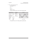


Step 2. Exchange the Input assemblies.
•
Set the power switch to off ( O ).
•
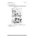
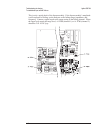
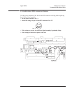
Exchange the Input assembly in the lower slot with the Input assembly in
the upper slot.
•
Reconnect the cables to the A5 Analog assembly.
•
Set the power switch to on ( l ).
•
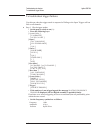
Press the following keys:
[
System Utility ]
[
CALIBRATN ]
[
AUTO CAL OFF ]
[
Input ]
[
ALL CHANNELS ]
[
CH* FIXED RANGE ]
1
[ Vpk ]
[
System Utility ]
[
MORE ]
[
SELF TEST ]
[
TEST LOG ]
[
Rtn ]
[
FUNCTIONL TESTS ]
[
INPUTS ]
[
ALL ]
[
CONTINUE ]
[
Rtn ]
[
Rtn ]
[
QUICK CONF TEST ]
•
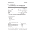
If the same channel fails as failed before the exchange, the A5 Analog
assembly is probably faulty.
•
If a different channel now fails, the A2 Input assembly for the failing
channel is probably faulty.
The Input assembly for channel 1 and 3 is in the lower slot. The Input assembly for
channel 2 and 4 is in the upper slot.
Agilent 35670A Troubleshooting the Analyzer
To troubleshoot input failures on four channel analyzers
4-55