


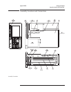

Voltages and Signals
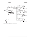
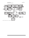
This chapter shows where the signals and voltages are used in the analyzer and
describes each signal. The signals are described in groups as shown in the
following table.
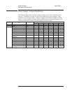
Section Title Describes signals routed ...
A1 Input through SMB cables from A1 Input to A5 Analog
A2 Input through SMB cables from A2 Input to A5 Analog
A8 Memory between A8 Memory and A7 CPU
A9 NVRAM between A9 NVRAM and A8 Memory
A10 Rear Panel between A10 Rear Panel and external connectors
A11 Keyboard Controller between A11 Keyboard Controller and A7 CPU
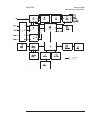
A12 BNC through A12 BNC
A13 Primary Keypad between A13 Primary Keypad and A11 Keyboard Controller
A14 Secondary Keypad between A14 Secondary Keypad and A11 Keyboard Controller
A22 BNC through A22 BNC
A99 Motherboard through A99 Motherboard
A100 Disk Drive between A100 Disk Drive and A7 CPU
A101 Display between A101 Display and A7 CPU
A102 DC-DC Converter between A102 DC-DC Converter and A101 Display
Note Signals with a mnemonic that end with a lower case ‘’n’’ are active low.
Signal levels listed as low or high are TTL levels unless stated otherwise.
Measurements given in dBm are terminated in 50 ohms unless stated otherwise.
9-2