


A13 Primary Keypad
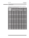
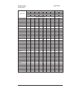
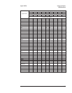
The following table lists signals routed between the A11 Keyboard Controller
assembly and the A13 Primary Keypad assembly. This table shows several things —
if the assembly generates or uses the signal. A description of each signal follows the
table.
Signal Name A11 Location
A11 A13
CHANA U1 pin 21
•S
CHANB U1 pin 6
•S
COL0 U1 pin 5
•S
COL1 U1 pin 4
•S
COL2 U1 pin 3
•S
COL3 U1 pin 2
•S
COL4 U1 pin 1
•S
COL5 U1 pin 27
•S
COL6 U1 pin 26
•S
COL7 U1 pin 25
•S
HRNGAn U3 pin 2
S•
HRNGBn U3 pin 4
S•
HRNGCn U3 pin 6?
S•
HRNGDn U3 pin 8?
S•
OVLDAn U2 pin 4
S•
OVLDBn U2 pin 5
S•
OVLDCn U2 pin 6
S•
OVLDDn U2 pin 7
S•
ROW0 U1 pin 13
•S
ROW1 U1 pin 14
•S
ROW2 U1 pin 15
•S
ROW3 U1 pin 16
•S
ROW4 U1 pin 17
•S
ROW5 U1 pin 22
•S
ROW6 U1 pin 23
•S
SRCn U2 pin 9
S•
+5 V U1 pin 19
••
Gnd U1 pin 12
••
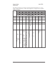
S This assembly is the source of the signal.
• This assembly uses the signal.
CHANA —
CHANB
These lines indicate the RPG’s direction and offset.
COL0 - COL7 Column 0 - Column 7 — A high-to-low transition on one column line indicates that a key in
that column was pressed. After the A11 Keyboard Controller assembly’s microprocessor
determines the keypad row location and the key number, the microprocessor sets columns 0 to
5 low which forces SINTFPn low. A high-to-low transition on SINTFPn informs the A7 CPU
assembly that a key was pressed.
HRNGAn
Agilent 35670A Voltages and Signals
A13 Primary Keypad
9-21