


Step 4. Check external trigger signal to the Analog assembly.
•
Set the power switch to off ( O ).
•
Remove the seven screws holding the rear panel to the analyzer and lean the
rear panel back until the A10 Rear Panel assembly is visible. Keep the
cables connected.
•
Set the power switch to on ( l ).
•
Change the frequency synthesizer’s amplitude to 2 Vp-p.
•
Set the oscilloscope as follows:
CH1 V/div
Input Impedance
CH1 Coupling
Time/div
Probe Atten
100 mV/div
1MΩ
dc
200 µs/div
10
•
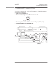
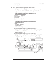
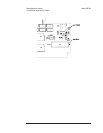
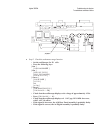
Connect the oscilloscope to A10 TP2 using a 10:1 probe.
•
Press the following keys:
[
Trigger ]
[
EXTERNAL TRIGGER ]
[
TRIGGER SETUP ]
[
EXT LEVEL USER ]
[
EXT RANGE +/− 10 ]
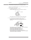
The oscilloscope should display a 370
40 mVp-p square wave.
•
If the signal is incorrect, the A10 Rear Panel assembly is probably faulty.
• Set the oscilloscope to 300 mV/div.
•
Press [ EXT RANGE +/ 2 ].
The oscilloscope should display a 1.9
0.2 Vp-p square wave.
•
If the signal is incorrect, the A10 Rear Panel assembly is probably faulty.
•
If the external trigger signals are correct, the A5 Analog assembly is
probably faulty.
Troubleshooting the Analyzer Agilent 35670A
To troubleshoot trigger failures
4-66