


•
Remove the A7 CPU assembly.
See ‘’To remove CPU’’ on page 6-11.
•
Set the power switch to on ( l ).
•
If the power supply LED is still off, set the power switch to off ( O ),
reconnect the CPU assembly, and go to Step 6.
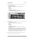
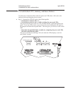
Step 5. Repeat the following steps until the assembly causing the Power Supply
assembly to shut down is located.
•
Set the power switch to off ( O ).
•
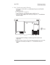
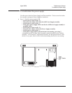
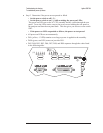
Reconnect one assembly at a time in the following order:
A7 CPU (A7 P10 to A99 J7)
A8 Memory (A8 P1 to A7 J3)
A102 DC-DC Converter (cable to A7 P2)
A11 Keyboard Controller (cable to A7 P1)
A100 Disk Drive (cable to A7 P3)
•
Set the power switch to on ( l ).
•
If the green power supply LED is off, the assembly just reconnected is
probably faulty.
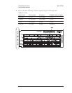
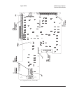
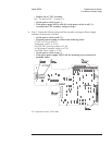
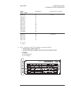
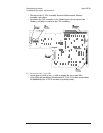
A7 Component Locator, Circuit Side
Agilent 35670A Troubleshooting the Analyzer
To troubleshoot the power supply
4-13