Configuration and Use Manual 63
Configuring Outputs
Configuring Batch Configuring Process MonitorConfiguring OutputsConfiguring Events
8.3 Configuring the discrete outputs
You can configure one, two, or three discrete outputs. For each discrete output, you will configure:
• Polarity
• Assignment
• Fault indication
Discrete outputs can be connected to factory-supplied or user-supplied relays. For relay installation
instructions, see Appendix D. For specifications of the Model 3100 relay supplied by Micro Motion,
see Appendix C.
8.3.1 Polarity
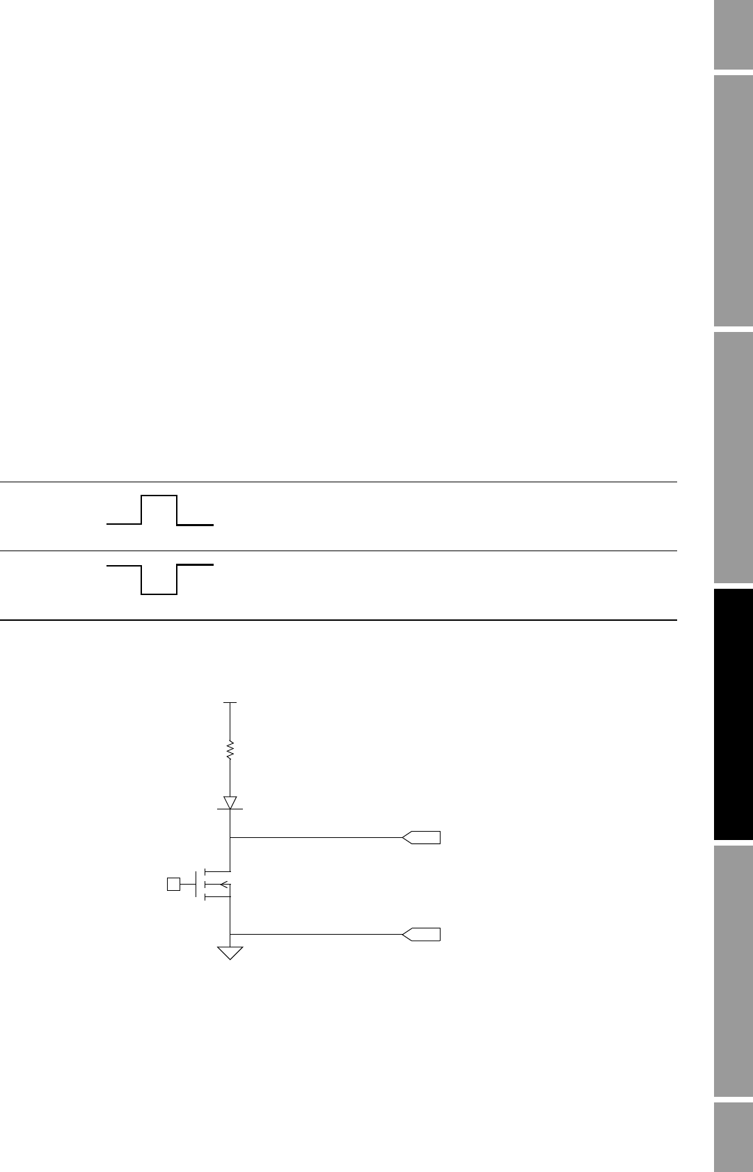
The discrete outputs generate two voltage levels to represent ON or OFF states. The voltage levels
depend on the output’s polarity, as shown in Table 8-1
. Figure 8-2 shows a diagram of a typical
discrete output circuit.
Figure 8-2 Discrete output circuit
Table 8-1 Discrete output polarity
Polarity Description
Active high • The circuit provides a pull-up to 24 V when asserted (when condition tied
to DO is true).
• The circuit provides 0 V when not asserted (when condition tied to the DO
is false).
Active low • The circuit provides 0 V when asserted (when condition tied to DO is
true).
• The circuit provides a pull-up to 24 V when not asserted (when condition
tied to the DO is false).
+24 V (Nom)
Out+
Out–
3.2 kΩ


