40 Micro Motion
®
Series 3000 MVD Transmitters and Controllers
Configuring Inputs
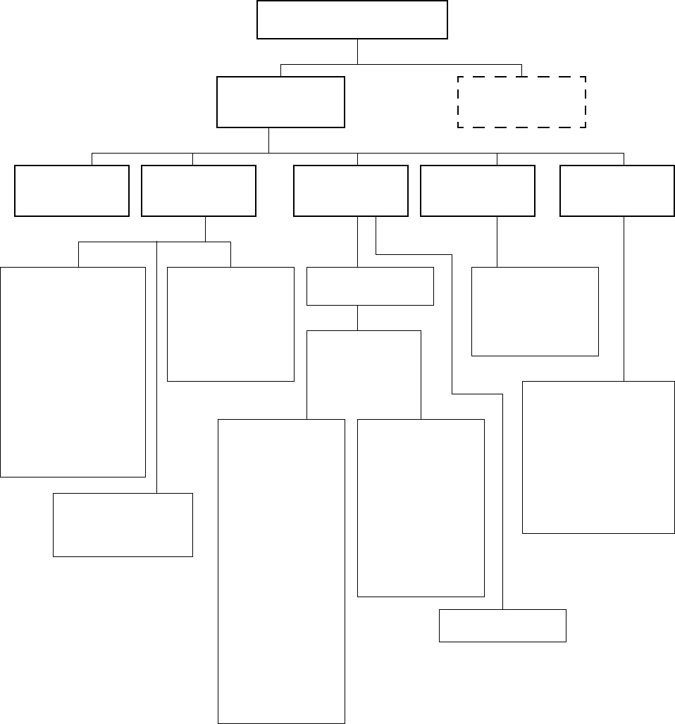
Figure 7-1 Inputs menu – Core processor parameters
Inputs
Flow variables
•Flow damping
• Flow direction
• Mass units
• Mass low flow cutoff
• Volume flow type
• Volume units
(2)
• Std gas volume units
(3)
•Std gas volume
cutoff
(3)(4)
• Std gas density
(3)
• Vol low flow cutoff
(2)
• Special mass units
• Special volume units
(2)
• Special gas std units
(3)
Enable/
Disable
Configure
process var
Sensor cal data
T-Series Setup
Core processor
(1)
Other inputs
See Figure 7-2
Ye s
•FCF
•FTG
•FFQ
•D1
•D2
•D3
•D4
•K1
•K2
•K3
•K4
•FD
•DT
•DTG
•DFQ1
•DFQ2
• Temp. slope
• Temp. offset
• Mass factor
• Density factor
• Volume factor
Density
• Density units
• Density damping
• Density cutoff
• Slug low limit
• Slug high limit
• Slug duration
No
•Flow cal
•D1
•D2
•K1
•K2
•FD
• Dens temp coeff
• Temp. cal factor
• Mass factor
• Density factor
• Volume factor
•Start zero
• Reset mass total
• Reset volume total
• Reset API cor vol tot
(5)
• Reset ED std vol tot
(6)
• Reset ED net mass to
(6)
• Reset ED net vol tot
(6)
• Reset all totals
• Start/stop all totals
• Start meter verify
(7)
Sensor
information
• Sensor model no.
• Sensor serial no.
• Sensor material
• Sensor flange
• Sensor liner
(1) Displayed only if you are configuring a Model 3500 or Model 3700 transmitter.
(2) Displayed only if Volume Flow Type = Liquid Volume.
(3) Displayed only if Volume Flow Type = Gas Standard Volume.
(4) Displayed only on systems with the enhanced core processor.
(5) Displayed only if petroleum measurement application is installed.
(6) Displayed only if enhanced density application is installed.
(7) Displayed only if Smart Meter Verification is installed.
Discrete inputs
Temperature
• Temperature units
• Temperature damping
LD Optimization


