238 Micro Motion
®
Series 3000 MVD Transmitters and Controllers
Diagnostics and Troubleshooting
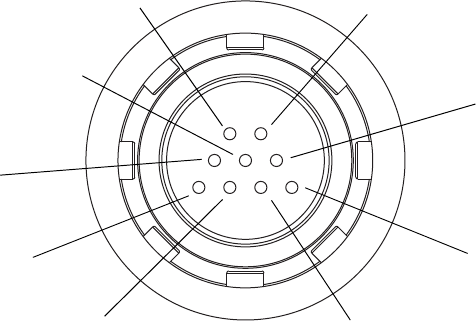
Figure 22-8 Sensor pins – Enhanced core processor
8. There should be no open circuits, i.e., no infinite resistance readings. The LPO and RPO
readings should be the same or very close (±5 Ω).
9. Using the DMM, check between each pin and the sensor case. With the DMM set to its highest
range, there should be infinite resistance on each lead. If there is any resistance at all, there is a
short to case. See Table 22-17 for possible causes and solutions.
10. Test terminal pairs as follows:
a. Drive + against all other terminals except Drive –
b. Drive – against all other terminals except Drive +
c. Left pickoff + against all other terminals except Left pickoff –
d. Left pickoff – against all other terminals except Left pickoff +
e. Right pickoff + against all other terminals except Right pickoff –
f. Right pickoff – against all other terminals except Right pickoff +
g. RTD + against all other terminals except LLC + and RTD/LLC
h. LLC + against all other terminals except RTD + and RTD/LLC
i. RTD/LLC against all other terminals except LLC + and RTD +
Note: D600 sensors and CMF400 sensors with booster amplifiers have different terminal pairs.
Contact Micro Motion customer service for assistance.
There should be infinite resistance for each pair. If there is any resistance at all, there is a short
between terminals. See Table 22-17 for possible causes and solutions.
11. If the problem is not resolved, contact Micro Motion customer service for assistance.
To return to normal operation:
Left pickoff –
Right pickoff –
Drive – Drive +
Right pickoff +
Left pickoff +
LLC / Composite RTD /
Fixed resistor
(1)
RTD +
(1) Functions as fixed resistor for the following sensors: F300, H300, F025A, F050A, F100A, CMF400 I.S., CMFS. Functions
as composite RTD for T-Series sensors. For all other sensors, functions as lead length compensator (LLC).
RTD –


