


Configuration and Use Manual 227
Diagnostics and Troubleshooting
Diagnostics and Troubleshooting Specifications – Model 3350/3700Specifications – Model 3300/3500Measurement Performance
22.11 Diagnosing wiring problems
Use the procedures in this section to check the transmitter installation for wiring problems.
22.11.1 Checking the power supply wiring
To check the power supply wiring:
1. Verify that the correct external fuse is used. An incorrect fuse can limit current to the
transmitter and keep it from initializing.
2. Power down the transmitter. If the transmitter is in a hazardous area, wait five minutes.
3. Ensure that the power supply wires are connected to the correct terminals. See the installation
instructions.
4. Verify that the power supply wires are making good contact, and are not clamped to the wire
insulation.
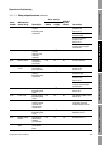
Consistently incorrect
frequency measurement
Output not scaled correctly Check frequency output scale and method. See
Section 22.15. Verify that voltage and resistance
match the frequency output load resistance
value chart.
Incorrect flow measurement unit
configured
Verify flow measurement unit configuration. See
Section 22.13.
Erratic frequency
measurement when flow is
stable
RF (radio frequency) interference from
environment
See Section 22.11.5.
Cannot connect to RS-485
terminals in service port
mode
Terminals not in service port mode Terminals are accessible in service port mode
ONLY for a 10-second interval after power-up.
Cycle power and connect during this interval.
Leads reversed Switch leads and try again.
Transmitter installed on multidrop
network
All Series 3000 devices on network default to
address=111 during 10-second service port
interval. Disconnect or power down other
devices, or use RS-485 communications.
Device is secured (custody transfer
only)
Change Series 3000 device to unsecured, or
use RS-485 communications.
Cannot connect to RS-485
terminals in RS-485 mode
Terminals not in RS-485 mode For the first 10 seconds after power-up, the
terminals are in service port mode. If a service
port connection is made during this period, they
remain in service port mode. Wait until
10-second interval has expired, cycle power to
the device to reset the terminals if required, or
connect in service port mode.
Incorrect RS-485 configuration After 10-second interval on power-up, the
transmitter switches to RS-485 mode. Default
settings are:
• Address=1
• Baud rate=9600
• Parity=odd
Use the display to check or change the RS-485
settings (see Section 13.3), then set parameters
appropriately in the remote device.
Leads reversed Switch leads and try again.
Table 22-9 I/O problems and remedies continued
Symptom Possible cause Possible remedy