


226 Micro Motion
®
Series 3000 MVD Transmitters and Controllers
Diagnostics and Troubleshooting
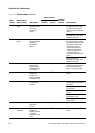
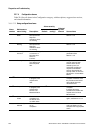
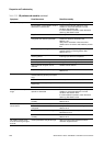
No frequency output Process condition below cutoff Verify or change the cutoff. See Section 8.4.4.
Fault condition if fault indicator is set to
downscale or internal zero
Check the fault indicator settings to verify
whether or not the transmitter is in a fault
condition. See Section 8.5.
If a fault condition is present, check the active
alarm log. See Section 22.6.
Slug flow See Slug flow alarms in Section 22.7.3.
Flow in reverse direction from
configured flow direction parameter
Verify process.
Check flow direction parameter. See
Section 7.3.2.
Verify sensor orientation. Ensure that flow
direction arrow on sensor case matches process
flow.
Bad frequency receiving device Check the frequency receiving device or try
another frequency receiving device. See
Section 22.11.6.
Output level not compatible with
receiving device
Verify that the output level and the required
receiving input level are compatible.
Bad output circuit Test output. See Section 16.4.4.
Incorrect pulse width configuration Verify pulse width setting. See Section 8.5.2.
Internal totalizer stopped and not
restarted
Restart internal totalizer.
Output is configured for passive power Ensure output power is set to active. See
Section 8.5.
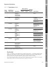
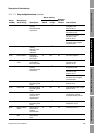
Constant mA output Non-zero HART address (multi-drop
communications) (primary mA output
only)
Set HART address to zero. See Section 22.11.7.
Output is fixed in a test mode Exit output from test mode. See Section 16.4.4.
Burst mode enabled (primary mA
output only)
Disable burst mode. See Section 13.4.
Zero calibration failure See Section 22.17.
mA output consistently out of
range
Fault condition if fault indicator is set to
upscale or downscale
Check the fault indicator settings to verify
whether or not the transmitter is in a fault
condition. See Section 8.4.2.
If a fault condition is present, check the active
alarm log. See Section 22.6.
20 mA and 4 mA values not set
correctly
Check the 20 mA and 4 mA values. See
Section 22.14.
Consistently incorrect mA
measurement
Output not trimmed correctly Trim the output. See Section 16.5.
Incorrect flow measurement unit
configured
Verify flow measurement unit configuration. See
Section 22.13.
Incorrect process variable configured Verify process variable assigned to mA output.
See Section 8.4.3.
20 mA and 4 mA values not set
correctly
Check the 20 mA and 4 mA values. See
Section 22.14.
mA reading correct at low
currents but wrong at higher
currents
mA loop resistance may be too high Verify mA output load resistance is below
maximum supported load.
Table 22-9 I/O problems and remedies continued
Symptom Possible cause Possible remedy