


230 Micro Motion
®
Series 3000 MVD Transmitters and Controllers
Diagnostics and Troubleshooting
22.17 Checking the calibration
Improper calibration can cause the transmitter to send unexpected output values. If the transmitter
appears to be operating correctly but sends inaccurate output values, an improper calibration may be
the cause.
Micro Motion calibrates every transmitter at the factory. Therefore, you should suspect improper
calibration only if the transmitter has been calibrated after it was shipped from the factory.
The calibration procedures in this manual are designed for calibration to a regulatory standard. To
calibrate for true accuracy, always use a measurement source that is more accurate than the flowmeter.
If there is significant discrepancy (>20%) between process data and the transmitter’s reported values,
do not attempt to recalibrate. Contact Micro Motion customer service for assistance.
Note: Micro Motion recommends using meter factors, rather than calibration, to prove the meter
against a regulatory standard or to correct measurement error. Contact Micro Motion before
calibrating your flowmeter. For information on meter performance verification, see Chapter 21.
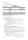
22.18 Checking the test points
Some status alarms that indicate a sensor failure or overrange condition can be caused by problems
other than a failed sensor. You can diagnose sensor failure or overrange status alarms by checking the
flowmeter test points. These values describe the current operation of the sensor.
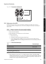
22.18.1 Obtaining the test points
To obtain current values for test points, use the Diagnostic Monitor, which is accessed from the View
menu. The Diagnostic Monitor displays:
• Tube frequency
• Left pickoff
• Right pickoff
•Drive gain
• Live zero
Note: The Diagnostic Monitor is not the same as the Diagnostics menu. The Diagnostics menu,
accessed through the Maintenance option of the Management menu, allows you to read the values of
external inputs and set output levels for outputs. The Diagnostics menu and its use are described in
Chapter 16.
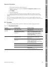
22.18.2 Evaluating the test points
Use the following guidelines to evaluate the test points:
• If the drive gain is unstable, refer to Section 22.18.3.
• If the value for the left or right pickoff does not equal the appropriate value from Table 22-10,
based on the sensor flow tube frequency, refer to Section 22.18.5.
• If the values for the left and right pickoffs equal the appropriate values from Table 22-10,
based on the sensor flow tube frequency, record your troubleshooting data and contact Micro
Motion customer service for assistance.