


228 Micro Motion
®
Series 3000 MVD Transmitters and Controllers
Diagnostics and Troubleshooting
5. Use a voltmeter to test the voltage at the transmitter’s power-supply terminals. Verify that it is
within the specified limits (see Appendix A or Appendix B).
22.11.2 Checking the sensor-to-transmitter wiring
To check the sensor-to-transmitter wiring, verify that:
• The transmitter is connected to the sensor according to the wiring information provided in the
installation instructions.
• The wires are making good contact with the terminals.
If the wires are incorrectly connected:
1. Power down the transmitter.
2. If the transmitter is in a hazardous area, wait five minutes.
3. Correct the wiring.
4. Restore power to the transmitter.
22.11.3 Checking grounding
The Series 3000 device must be grounded. If you are using a T-Series sensor, it must be grounded. If
the core processor is installed separately, it must be grounded separately. See the installation
instructions.
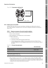
22.11.4 Checking the HART communication loop
To check the HART communication loop (primary mA output only):
1. Verify that the loop wires are connected correctly for HART/analog wiring.
2. Remove analog loop wiring.
3. Install a 250 Ω resistor across the primary mA output terminals.
4. Check for voltage drop across the resistor (4–20 mA = 1–5 VDC). If voltage drop < 1 VDC,
add resistance to achieve voltage drop > 1 VDC.
5. Connect the Communicator directly across the resistor and attempt to communicate (poll).
22.11.5 Checking for RF interference
If you are experiencing RF (radio frequency) interference on your frequency output or discrete output,
use one of the following solutions:
• Eliminate the RF source. Possible causes include a source of radio communications, or a large
transformer, pump, motor, or anything else that can generate a strong electrical or
electromagnetic field, in the vicinity of the transmitter.
• Move the transmitter.
• Use shielded cable for the frequency output.
- Terminate output cable shielding at the input device. If this is not possible, terminate the
output shielding at the cable gland or conduit fitting.
- Do not terminate shield inside the wiring compartment.
- 360° termination of shielding is not necessary.