


Configuration and Use Manual 233
Diagnostics and Troubleshooting
Diagnostics and Troubleshooting Specifications – Model 3350/3700Specifications – Model 3300/3500Measurement Performance
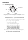
Table 22-14 Standard core processor LED behavior, flowmeter conditions, and remedies
LED behavior Condition Possible remedy
1 flash per second
(ON 25%, OFF 75%)
Normal operation No action required.
1 flash per second
(ON 75%, OFF 25%)
Slug flow See Section 22.7.3.
Solid ON Zero or calibration in
progress
If calibration is in progress, no action required. If no calibration is in
progress, contact Micro Motion.
Core processor
receiving between 11.5
and 5 volts
Check power supply to transmitter.
3 rapid flashes,
followed by pause
Sensor not recognized Check wiring between transmitter and sensor. See Section 22.11.2.
Improper configuration Check sensor characterization parameters. See Section 22.16.
Broken pin between
sensor and core
processor
Contact Micro Motion.
4 flashes per second Fault condition Check alarm status. See Section 22.6.
OFF Core processor
receiving less than 5
volts
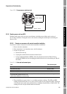
• Verify power supply wiring to core processor. See Section 22.11.2
.
• If transmitter display is lit, transmitter is receiving power. Check
voltage across terminals 1 (VDC+) and 2 (VDC–) in core processor.
Normal reading is approximately 14 VDC. If reading is normal,
internal core processor failure is possible. Contact Micro Motion. If
reading is 0, internal transmitter failure is possible. Remove the wires
from core processor terminals 1 and 2, and check the voltage across
the wires. If the voltage reading is now ~14 VDC, the transmitter is
normal. If the voltage reading is not ~14 VDC, contact Micro Motion.
If reading is less than 1 VDC, verify power supply wiring to core
processor. Wires may be switched. See Section 22.11.2.
• If transmitter display is not lit, transmitter is not receiving power.
Check power supply. If power supply is operational, internal
transmitter or display failure is possible. Contact Micro Motion.
Core processor
internal failure
Contact Micro Motion.
Table 22-15 Enhanced core processor LED behavior, flowmeter conditions, and remedies
LED behavior Condition Possible remedy
Solid green Normal operation No action required.
Flashing yellow Zero in progress If calibration is in progress, no action required. If no calibration is in
progress, contact Micro Motion.
Solid yellow Low severity alarm Check alarm status.
Solid red High severity alarm Check alarm status.
Flashing red (80% on,
20% off)
Tubes not full If alarm A105 (slug flow) is active, see Slug flow alarms in
Section 22.7.3.
If alarm A033 (tubes not full) is active, verify process. Check for air in
the flow tubes, tubes not filled, foreign material in tubes, or coating in
tubes.
Flashing red (50% on,
50% off)
Electronics failed Contact Micro Motion.