


84 Chapter 2
Programming Fundamentals
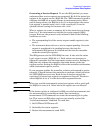
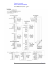
Using the Instrument Status Registers
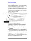
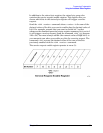
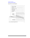
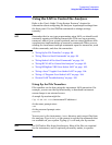
To query the status byte register, send the command *STB? The
response will be the decimal sum of the bits which are set to 1. For
example, if bit number 7 and bit number 3 are set to 1, the decimal sum
of the 2 bits is 128 plus 8. So the decimal value 136 is returned. The
*STB command does not clear the status register.
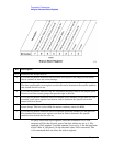
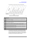
Bit Description
0, 1 These bits are always set to 0.
2 A 1 in this bit position indicates that the SCPI error queue is not empty which means
that it contains at least one error message.
3 A 1 in this bit position indicates that the data questionable summary bit has been set.
The data questionable event register can then be read to determine the specific condition
that caused this bit to be set.
4 A 1 in this bit position indicates that the instrument has data ready in the output queue.
There are no lower status groups that provide input to this bit.
5 A 1 in this bit position indicates that the standard event summary bit has been set. The
standard event status register can then be read to determine the specific event that
caused this bit to be set.
6 A 1 in this bit position indicates that the instrument has at least one reason to report a
status change. This bit is also called the master summary status bit (MSS).
7 A 1 in this bit position indicates that the standard operation summary bit has been set.
The standard operation event register can then be read to determine the specific
condition that caused this bit to be set.