


Agilent N5161A/62A/81A/82A/83A MXG Signal Generators User’s Guide 83
Preliminary Optimizing Performance
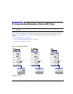
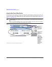
Preliminary Using the Dual Power Meter Display
Example: Dual Power Meter Calibration
In the following example a U2004A USB Power Sensor is connected to channel A and a N1912A
P–Series Power Meter and 8482A Power Sensor are connected to channel B and are zeroed and
calibrated, as required.
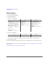
On the MXG:
1. Setup MXG for Step Sweep. “Configuring a Swept Output” on page 48.
CAUTION Verify RF Output power is off before continuing.
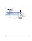
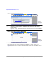
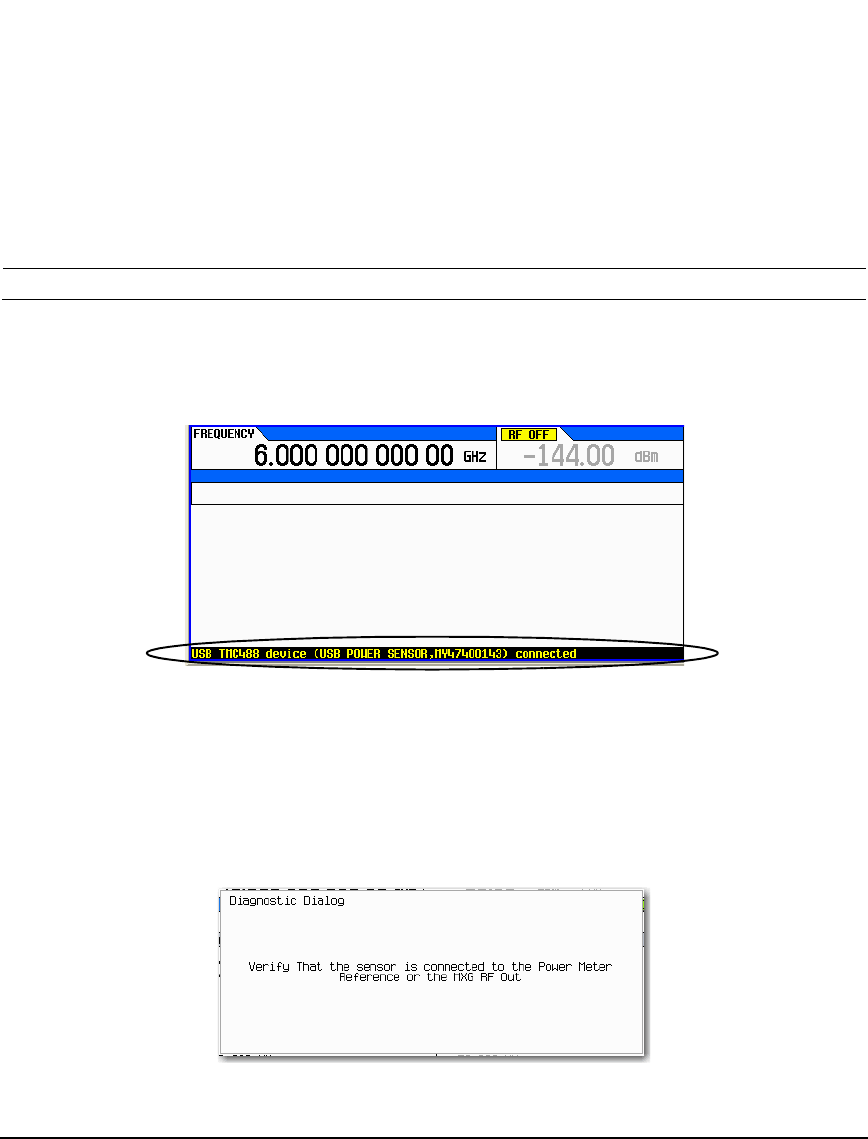
2. Connecting the Channel A power sensor: Connect USB sensor to MXG. The MXG should display a
message across the bottom that reads similar to:
USB TMC488 device (USB POWER SENSOR,MY47400143) connected
Figure 5-4 MXG Displays Connection to U2000 USB Power Sensor
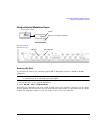
3. Press Aux Fctn > Power Meter Measurements > Channel A Setup > Connection Settings > Connection Type >
USB Device (None) > USB POWER SENSOR (MY47400143)
4. Press Return > Zero Sensor
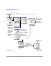
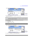
A diagnostic dialog box appears the initial time that a U2000 Series power sensor with a
different serial number is connected to the MXG (refer to Figure 5-5). After the U2000 has been
recognized by the MXG, the U2000 power sensor is saved as a softkey in the instrument and the
dialog box in Figure 5-5 won’t be displayed (press DONE, if you see this message).
Figure 5-5 Diagnostic Dialog Box for USB Sensor
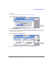
A Running Calibration(s) bar is displayed on the MXG. Refer to Figure 5- 6 on page 84.