


106 Agilent N5161A/62A/81A/82A/83A MXG Signal Generators User’s Guide
Optimizing Performance Preliminary
Using Unleveled Operating Modes Preliminary
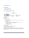
7. Adjust the signal generator’s amplitude until the power meter measures the desired level.
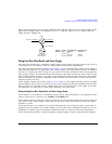
Power Search Mode
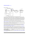
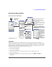
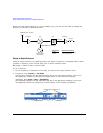
Refer to Figure 5-20 on page 105. Power search executes a routine that temporarily activates the
ALC, calibrates the power of the current RF output, and then disconnects the ALC circuitry.
The four Power Search References control the power search function.
• Fixed – Reference level is 0.5 Vrms.
This reference functions with internal, external IQ and bursted signals. This is the instrument’s
default setting.
• RMS – User provided reference level 0–1.4 Vrms placed in the Waveform Header.
This reference functions with internal IQ and bursted signals.
• Manual – User provided reference level 0–1.4 Vrms.
This reference functions with internal, external IQ and bursted signals.
• Modulated – Uses the I/Q modulation signal as the reference level.
This reference functions with internal or external IQ. It is not functional with bursted signals or
a signal with varying Vrms.
The RMS and MANUAL references are the most powerful selections. The user provides the reference
level. The IQ signal can be bursted (radar) or have different RMS levels (Wireless Signals). Once the
RMS level is set, the power search runs independent of the current Vrms value of the waveform.
The RMS and MANUAL references, with a reference level of 1.0 Vrms are equivalent to a FIXED
reference and is measured using SINE_TEST_WFM.
The FIXED, RMS, and MANUAL references use a DAC to apply the reference voltage and do not
require the IQ signal to be present.
CAUTION The minimum reference level that results in a successful power search is dependent on
RF Frequency, RF Amplitude, and Temperature. An MXG power search using a reference
level of 0.1 Vrms for 0 dBm at 1 GHz may fail.
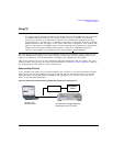
Power Search Settings
For the power search routine to execute, the instrument must be in the following conditions:
• The I/Q modulation enabled On.
• The RF output enabled On.
• The Automatic Leveling Circuitry deactivated (Off).
• The RF Blanking set to On.
This function prevents power spikes during the power search (refer to “Using the RF Blanking
Marker Function” on page 158.)
• When using FIXED, RMS, or MANUAL send zeros (no signal) to the IQ modulator.