


88 Agilent N5161A/62A/81A/82A/83A MXG Signal Generators User’s Guide
Optimizing Performance Preliminary
Using Flatness Correction Preliminary
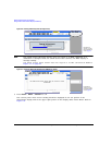
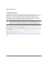
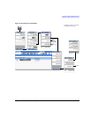
Using Flatness Correction
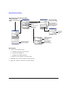
User flatness correction allows the digital adjustment of RF output amplitude for up to 1601
sequential linearly or arbitrarily spaced frequency points to compensate for external losses in cables,
switches, or other devices. Using an Agilent N1911A/12A, E4419A/B, or U2000 Series power
meter/sensor to calibrate the measurement system, a table of power level corrections can
automatically be created for frequencies where power level variations or losses occur. Supported
connection types to the power meter/sensor are Sockets LAN, VXI–11 LAN, USB, and GPIB via
VXI–11 LAN using a LAN–GPIB gateway (e.g. E5810A Gateway or equivalent).
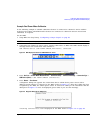
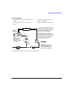
NOTE A power meter with GPIB requires using the Connection Type VXI–11 softkey, as well as a
LAN–GPIB gateway, to control a power meter. Refer to the Agilent Connectivity Guide
USB/LAN/GPIB Connectivity Guide (E2094–90009), Agilent MXG’s FAQs “How do I connect
to the LAN?”, and to the E5810A User’s Guide or equivalent, LAN/GPIB gateway device.
If you do not have an Agilent N1911A/12A or E4419A/B power meter, or U2000A/01A/02A/04A
power sensor, or if your power meter does not have a LAN, GPIB, or USB interface, the correction
values can be manually entered into the signal generator.
To allow different correction arrays for different test setups or different frequency ranges, you may
save individual user flatness correction tables to the signal generator’s memory catalog and recall
them on demand.
Follow the steps in the next sections to create and apply user flatness correction to the signal
generator’s RF output (see page 92).
Afterward, follow the steps in “Recalling and Applying a User Flatness Correction Array” on page 96
to recall a user flatness file from the memory catalog and apply it to the signal generator’s RF
output.