


Agilent N5161A/62A/81A/82A/83A MXG Signal Generators User’s Guide 149
Preliminary Basic Digital Operation (Option 651/652/654)
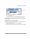
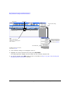
Preliminary Using Waveform Markers
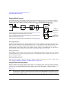
ALC Hold Marker Function
While you can set a marker function (described as Marker Routing on the softkey label) either before
or after you set marker points (page 154), setting a marker function before setting marker points may
cause power spikes or loss of power at the RF output.
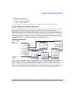
Use the ALC hold function by itself when you have a waveform signal that incorporates idle periods,
burst ramps, or when the increased dynamic range encountered with RF blanking (page 158) is not
desired.
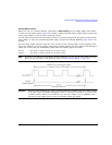
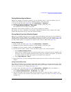
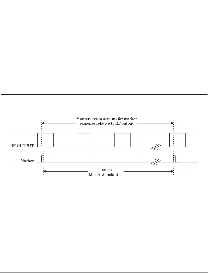
The ALC hold marker function holds the ALC circuitry at the average value of the sampled points
set by the marker(s). For both positive and negative marker polarity, the ALC samples the RF output
signal (the carrier plus any modulating signal) when the marker signal goes high:
NOTE Because it can affect the waveform’s output amplitude, do not use the ALC hold for longer
than 100 ms. For longer time intervals, refer to “Power Search Mode” on page 106.
CAUTION Incorrect ALC sampling can create a sudden unleveled condition that may create a spike
in the RF output, potentially damaging a DUT or connected instrument. To prevent this
condition, ensure that you set markers to let the ALC sample over an amplitude that
accounts for the higher power levels encountered within the signal.
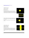
Positive: The signal is sampled during the on marker points.
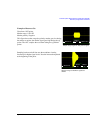
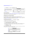
Negative The signal is sampled during the off marker points.
Positive Polarity